
Version du 04/12/2006 – traduction by Nap0
The purpose of this document is to explain how to create missions
for Flight Simulator X. A mission is a structured flight that
can be an adventure, a tutorial, a test of knowledge or skill, a fun
ride, or whatever the creator can dream up. These missions are stored
in XML files and are made available to the user through the Missions
menu of Flight Simulator X.
Le but
de ce document est d'expliquer comment créer des missions dans
FSX. Une mission est un vol vol organisé qui peut être
une aventure, un tutoriel, un test de connaissance or skill, une
course ou encore tout ce que vous pouvez imaginer. Les missions sont
stockées dans des fichiers XML et sont disponibles par le menu
mission de FSX
Creating Missions involves use of the Object Placement Tool,
which is powerful but not the easiest or most obvious tool to use.
La création de missions nécessite
d'utiliser l'outil de placement d'objets, il est puissant mais ce
n'est pas le plus simple a utiliser.
The Tutorial
section of this document explains how to install the tool, how to
create a simple mission using it, and how to add that Mission so
that it shows up in Flight Simulator X.
Cette
section explique comment installer l'outil, comment créer une
simple mission et comment l'ajouter dans les missions de FSX
The
Reference section of this document explains all the options available
to make more complex and involved missions.
La
section Référence décrit toutes les options
disponible pour créer des missions très complexes.
The tool itself is coded in Object_Placement.dll.
Object_Placement.dll can be found in the Microsoft Flight
Simulator X\SDK\Mission Creation Kit directory.
L'outil
lui-même est codé dans la DLL Object_Placement.dll. On
peut le trouver dans le dossier Microsoft Flight Simulator
X\SDK\Mission Creation Kit
To install the dll,
the dll.xml file in the <Drive>:\Documents and
Settings\<alias>\Application Data\Microsoft\FSX folder
should contain the following bold lines (if the dll.xml file already
exists in this folder), or the dll.xml file should contain all the
following (if the dll.xml file does not already exist at the right
location).
Pour installer la dll, le
fichier dll.xml dans le dossier <Drive>:\Documents and
Settings\<alias>\Application Data\Microsoft\FSX doit
contenir les lignes en gras ci-dessous. Si le fichier n'existe pas,
il faut le créer avec le contenu ci-dessous
|
<?xml version="1.0" encoding="Windows-1252"?> <SimBase.Document
Type="Launch"
version="1,0">
</SimBase.Document> |
Note that the Disabled entries must be False, and that the
Path is either absolute or relative to the installation Microsoft
Flight Simulator X folder. The path given above will change if
the SDK or Flight Simulator were not installed to their
default folders. If there are other addons that need to be loaded in
addition to the Object Placement tool, then they will also need
<Launch.Addon> entries.
This is all the setup that is
necessary.
Remarquez que l'entrée
Disabled doit être à False et que le chemin peut être
absolu ou relatif. Si il y a d'autres addons, il seront déclarés
dans la section <Lauch.Addon>
You will know that Flight Simulator has correctly installed
the tool when you start up Flight Simulator. Firstly there
will be a diagnostic window for SimConnect that should report that
the dll has been launched. Secondly the tool will be available in the
Tools menu of Flight Simulator.
Vous
saurez si l'outil est correctement installé quand vous
démarrerez FS. Premièrement une fenêtre de
diagnostic pour SimConnect doit vous indiquer qu'une DLL a été
lancée. Deuxièmement, le logiciel sera disponible dans
le menu Outils de FS
Ensure that Flight
Simulator is running in Windows mode and not full screen mode
(you can toggle between these modes by pressing
Alt-Enter).
Assurez-vous que FS
fonctionne en mode fenêtre et non pas plein écran
(touche Alt-Enter)
If you get an error message in
the SimConnect diagnostic window, check the SimConnect.xml file for
the correct path to the tool, and check the tool is where is should
be.
Si vous rencontrez un message
d'erreur dans SimConnect, vérifiez le fichier
SimConnect.xml
If the tool has been installed
correctly, clicking on Object Placement in the Tools menu will give
you the dialog below:
Si l'outil a été
installé correctement, Cliquer sur Object Placement dans le
menu Outils et vous obtiendrez la fenêtre suivante :
Close Flight Simulator for now. The first step in creating a
mission is done outside of the program.
Maintenant,
fermez FS. La première étape se réalise en
dehors du programme
This section goes through all the steps necessary to create a
simple take-off, perform a single task, and landing mission.
Cette
section montre toutes les étapes pour créer une simple
mission : Décollage, réaliser une simple opération,
atterrir
For experienced mission designers it is a very good idea to
design the mission in some detail before even starting to use the
tool to create it. However for newcomers to the tool it is easier
simply to start with a basic outline. For the purposes of this
tutorial in how to use the tool, the outline of our mission is:
Il
est préférable pour créer une mission de la
planifier auparavant dans les détails et d'en commencer la
programmation même si l'outil peut semble simple à
prendre en main. Pour ce tutoriel, le programme de la mission est le
suivant :
Fly a Cessna out of Boeing Field
Reach a certain altitude and speed (1000 feet and 80 knots)
Complete a left or right traffic pattern
Land back at Boeing Field, trying to land on the runway number
When the aircraft has landed, the mission is over
Vol en Cessna à partir de Boeing Field
Atteindre l'altitude de 1000 pieds et 80 noeuds
Réaliser un virage à droite ou à gauche
Revenir à l'aéroport en essayant de se poser sur le numéro de piste
Quand l'avion à atteri, la mission est terminée
The mission will simply be called MissionCreationTutorial.
Le
nom de la mission sera MissionCreationTutorial
Having
decided on this the next stage is to do a bit of preparatory work
before working the tool. Flight Simulator loads up the
missions that are in the Microsoft Flight Simulator X/missions
directory, so start by adding a sub-directory to this
called Missions in Progress, and a sub-directory to this
called Creation Tutorial.
Nous
allons dans cette étape préparer le travail avant
d'utiliser l'outil. FS charge les missions qui sont dans le
répertoire Microsoft Flight Simulator X/missions.
Commençons par créer un sous répertoire
appelé Missions in Progress et un autre appelé
Creation Tutorial
Now add three files to the
Creation Tutorial directory: two images files and one HTML
briefing file. The two image files should be square and will appear
in the Missions list of Flight Simulator. The first will be
used before the mission has been completed by the user, and the
second for when the mission has been completed. The images
should be 380 pixels wide by 232 pixels in height and either 256
color or 5-6-5 format (use the Imagetool utility to convert 24 bit
bmp files to 5-6-5 format.). The image should give some idea of what
the mission is about. For our tutorial we will use a simple picture
of a Cessna:
Maintenant, ajoutons 3
fichiers dans le dossier Creation Tutorial. 2 fichiers image
et un fichier HTML contenant le briefing. La première sera
utilisée juste avant la fin de la mission et l'autre à
la fin de la mission. L'image doit faire 380x232 pixels et au moins
256 couleurs ou alors le format 5-6-5 (utilisez Imagetool pour
convertir les bmp 24 bits au format 5-6-5). L'image doit donner une
idée de ce que sera la mission. Pour notre tutoriel, nous
utiliserons simplement une image de Cessna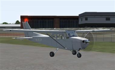
The
briefing file should be an HTML file describing the mission. You will
probably not be able to complete the briefing file until the final
mission is completed and tested, but for now use one of the images
and our mission description. For example:
Le
fichier HTML du briefing décrit la mission. Il sera
probablement complété quand la mission aura été
créée et testée. Par exemple :
Mission Creation Tutorial
|
|
Fly a Cessna out of Boeing Field, reach a certain altitude and speed (1000 feet and 80 knots), then land back at Boeing Field. |
In summary the Creation Tutorial directory now contains
three files:
Cessna_Complete.jpg
Cessna_Incomplete.jpg
MissionCreationTutorial.HTML
En résumé, le dossier Creation Tutorial contient maintenant 3 fichiers : Cessna_complete.jpg, Cessna_Incomplete.jpg et MissionCreationTutorial.HTML
The next step is to create metadata for the mission. Some of this
information is simply for your own use in organizing and retrieving
the missions that you are working on. Start up Flight Simulator
again, and select FREE FLIGHT. For aircraft select the Cessna C172P
Skyhawk and for airport select Boeing Field King Co Intl. Then select
Fly Now and click on the Object Placement Tool from the tools
menu.
L'étape suivante consiste a
créer les méta données pour la mission. Démarrez
FS et sélectionnez Vol libre. Choisissez Cessna C172P Skyhawk
et l'aéroport Boeing Field King Co Intl (KBFI). Cliquez sur
Voler Maintenant puis sur Object Placement dans le menu Outils.
In
the main Mission tab, first click New Mission then enter a suitable
name and description. Enter Mission Creation Tutorial for
the name, and some appropriate text for the description. These do not
appear when the mission is being run, but are simply for your own use
in cataloging and maintaining your own missions. Next click on the
Objects tab, this will give you the following screen:
Sur
l'onglet Mission, cliquez sur New Mission et entrez un nom et une
description. Par exemple Mission Creation Tutorial pour le nom
et le texte «qui va bien» pour la description. Ceci
n'apparaîtra pas quand la mission sera lancée. C'est
simplement pour des raisons de classement et d'organisation. Ensuite,
cliquez sur l'onglet Objects. Ce qui donnera l'écran
suivant.
Click
on the Add button, then in the First drop down list (activated by
clicking within the box) select MissionObject. Click in the Second
box to display the drop down list of mission objects, and select
ScenarioMetadata. Click on Add again and the dialog should look like
this:
Cliquez sur la bouton Add, dans la
première liste déroulante, choisissez MissionObject.
Cliquez sur la seconde liste des objets missions et choisissez
ScenarioMetadata. Cliquez encore sur Add et la fenêtre doit
afficher donner ceci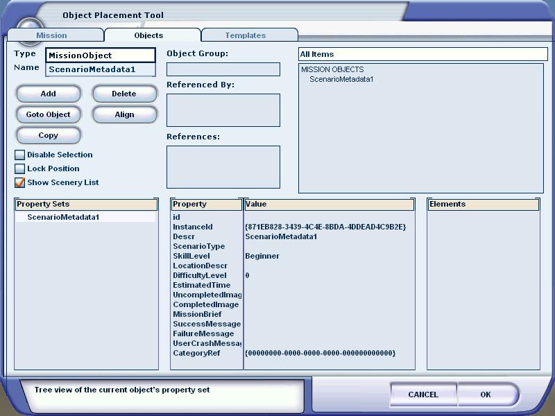
The next step is to add the appropriate values for the properties of
the metadata. To edit any value double click on the entry in the
Value box. For our simple mission, enter Mission into
ScenarioType, Seattle into LocationDesc, select Beginner
for skill level, and enter 15 minutes for EstimatedTime.
The DifficultyLevel can be any integer value, and is used to sort the
list of missions by difficulty - easiest appearing first. Leave this
at 0 so that the mission appears at the top of the list each
time you start Flight Simulator, for convenience. When you
have completed creating the mission, if it is to be used by others,
then compare the difficulty (and the DifficultyLevel value) with
other missions and then change this to an appropriate value.
L'étape
suivant consiste à donner des valeurs appropriées aux
méta données. Pour éditer une valeur,
double-cliquez sur le champ Value. Pour notre mission, entrons
Mission dans ScenarioType, Seattle dans LocationDesc,
Beginner pour le niveau et 15 minutes pour EstimatedTime.
DifficultyLevel pour être n'importe quelle valeur entière.
Elle est utilisé pour trier l'ordre des missions par
difficulté. Les plus faciles apparaissent en premier. Mettez 0
pour que celle-ci apparaissent en haut chaque fois que vous lancerez
FS. Lorsque vous aurez terminé de créer la mission et
après plusieurs essais par vous même et d'autres vous
aurez peut être besoin d'ajuster cette
valeur.
UncompletedImage refers to the bitmap that
is to be displayed before the mission has been completed by the user,
so type Cessna_Incomplete.jpg here, and obviously the
CompletedImage refers to the bitmap that will be used when the
mission has been completed, so type Cessna_Complete.jpg. For
MissionBrief type MissionCreationTutorial.HTML. It is
important not to add a filename to the metadata until that file
acutally exists, otherwise the tool may crash. This is why we created
the briefing file and images first.
UncompletedImage
fait référence à une bitmap qui sera affiché
juste avant que la mission sera terminée.Dans notre exemple,
Cessna_Incomplete.jpg. CompletedImage fait référence
à une bitmap qui sera affichée lorsque la mission sera
terminée, ici Cessna_Complete.jpg
Pour MissionBrief, tapez MissionCreationTutorial.HTML. Il est
important de ne pas ajouter les noms de fichiers tant que ceux
n'existent pas car cela peut planter l'outil. C'est la raison pour
laquelle nous les avons créés en premier.
Leave
the text messages and CategoryRef unchanged for now.
Laissez
les messages de texte et CategoryRef en l'état pour le
moment.
Now save off the mission, by going back to
the Mission tab and clicking Save Mission. The default is
to save the mission file into your My Documents\Flight
Simulator Files X directory, but instead navigate to the
Microsoft Flight Simulator X\missions\Missions in
Progress\Creation Tutorial directory, and save the mission there
with the filename MissionCreationTutorial. Saving a mission will
write out the details of the mission to an XML file. If you open up
the file that has just been saved it should look similar to
this:
Maintenant, sauvez la mission en
retournant sur l'onglet Mission et cliquez sur Save Mission. Par
défaut, la mission sera sauvée dans My
Documents\Flight Simulator Files X mais à la place allez
dans le répertoire Microsoft Flight Simulator
X\missions\Missions in Progress\Creation Tutorial et sauvegardez
la sous le nom MissionCreationTutorial. Ceci avec générer
un fichier XML contenant les détails de celle-ci. Si vous
ouvrez ce fichier, vous devriez y trouver quelque chose comme
ci-après.
|
<?xml
version="1.0" encoding="Windows-1252"
?> <Filename>C:\Program Files\Microsoft Games\Microsoft Flight Simulator X\missions\Missions in Progress\Creation Tutorial\MissionCreationTutorial.xml</Filename> <Title>Mission Creation Tutorial</Title> <WorldBase.Flight> <SimMissionUI.ScenarioMetadata InstanceId="{871EB828-3439-4C4E-8BDA-4DDEAD4C9B2E}"> <Descr>ScenarioMetadata1</Descr> <ScenarioType>Mission</ScenarioType> <LocationDescr>Seattle</LocationDescr> <DifficultyLevel>0</DifficultyLevel> <EstimatedTime>15
minutes</EstimatedTime> </SimMissionUI.ScenarioMetadata> </WorldBase.Flight> <MissionBuilder.MissionBuilder
/> |
Now is a good time to enter the category of your mission. The
category (referenced by a GUID in the CategoryRef property of
the metadata) will idenfity the mission as one from the
following list:
Maintenant le moment est
venu d'entrer la catégorie de votre mission. La catégorie
(GIUD dans la propriété CategoryRef des métadonnées)
identifiera la mission parmi la liste suivante :
Tutorial
Just for Fun
The Good Life
Backcountry
Pilot for Hire
Emergency
Airline Pilot
Challenges
To set the category GUID in your metadata cut and paste the value
out of this Category
file. We will use the Tutorial category for this mission.
Typically a tool such as Notepad is used to make this kind of edit to
the mission data. Make sure to include the brackets {} when you cut
and paste the GUID.
Pour renseigner la
catégorie dans les métadonnées (CategoryRef) ,
copiez-collez la valeur du fichier Category
File (FSCategories.xml). Ce fichier s'ouvre avec le
bloc-notes (ou autres) et récupérez la valeur entre les
crochets {} et avec les crochets.
|
<?xml
version="1.0" encoding="UTF-16" ?>
<SimMissionUI.ScenarioCategory
id="{GUID}"> </SimBase.Document> |
The next step is to link the mission we have just started to a
flight file. It is flights that are loaded into Flight Simulator,
not missions, so we need to attach the two. If you have not done so
already, at the start of Step 2, set up the starting location
within Flight Simulator, namely create a flight with your
chosen aircraft at the chosen airport. For this sample mission, we
are using a Cessna at Boeing Field airport.
L'étape
suivante consiste à lier la mission que nous avons commencé
avec un fichier de vol. Ce sont les vols qui sont chargés dans
Flight Simulator, pas les missions, ainsi nous avons besoin de lier
les deux. Si vous n'avez pas déjà fait ce que est au
début du point 2, sélectionnez la position de départ
dans Flight Simulator en créant un vol en choisissant un avion
et un aéroport. Pour cette exemple, nous utilisons un Cessna
sur l'aéroport Boeing Field.
Having placed your aircraft at the right location, simply
select Save Flight from the Flights menu and save it off. Name the
saved file MissionCreationTutorial. Now close Flight
Simulator.
Après avoir placé
l'avion au bon endroit, sauvegardez le vol et nommez le
MissionCreationTutorial. Maintenant fermez FS
Next
go to the My Documents\Flight Simulator Files X directory and
cut and paste (or move) the flight file and weather file of the
flight that you just saved over to the location where you saved the
mission. In our example, the mission was saved to the Missions in
Progress\Creation Tutorial directory, which, after moving the
flight and weather files, should now contains six files:
Ensuite
allez dans le dossier Mes Documents\Flight Simulator Files X
et coupez collez le fichier de vol et de météo que vous
venez de sauvegarder. Sans notre exemple, la mission a été
sauvegardée dans le répertoire Progress\Creation
Tutorial. Après cette opération, nous devons
trouver six fichiers.
MissionCreationTutorial.xml
MissionCreationTutorial.FLT
MissionCreationTuturial.WX
Cessna_Complete.jpg
Cessna_Incomplete.jpg
MissionCreationTutorial.HTML
MissionCreationTutorial.xml
MissionCreationTutorial.FLT
MissionCreationTutorial.WX
Cessna_Complete.jpg
Cessna_Incomplete.jpg
MissionCreationTutorial.HTML
In the Creation Tutorial directory, open up the flight file
(MissionCreationTutorial.FLT) in Notepad.
Dans
le répertoire Creation Tutorial, ouver à l'aide
du bloc-note (ou un autre éditeur) le fichier
MissionCreationTutorial.FLT
The first section of a
flight file should be [Main]. Under this should be Title=
and Description=. This is the text that will appear as the
title and description for the mission in the Missions menu (along
with the image file created earlier), so edit the text, perhaps
adding spaces, so that it is what you want. For example:
La
première section du fichier de vol doit être [Main].
ensuite ce doit être Title= et Description=. C'est le texte qui
apparaitra comme le titre et la description de la mission dans le
menu des missions (avec l'image créée plus haut).
Editez le texte selon votre souhait. Par exemple :
[Main]
Title=Mission Creation
Tutorial
Description=Décoller et voler !
Now
go to the very end of the file and type the following section
entry:
Maintenant allez tout à la
fin du fichier et ajouter la section suivante
:
[ObjectFile]
File=MissionCreationTutorial
Note
that the xml file extension is not added to the filename, and that
there are no spaces around the equals signs. This links the mission
to the flight file.
Notez que l'extension
xml n'est pas ajoutée au nom du fichier et qu'il n'y a pas
d'espace autour du signe égal. Ceci fait la liaison avec le
fichier de vol.
Now save off the flight
file.
Maintenant sauvez et fermez le
fichier
The next step is simply to test what we have done so far. Start up
Flight Simulator, select Missions in the left hand menu, and
check that the Mission Creation Tutorial has appeared with the
correct image and text.
L'étape
suivante consiste simplement à tester ce que nous avons fait
précédemment. Démarrer FS, sélectionnez
le menu Missions et vérifiez que la mission : Mission Creation
Tutorial apparait avec la bonne image et le bon texte
Select the mission. The first thing that should appear is the
short briefing file we created. Then click Fly Now. You should be
sitting on the runway in a Cessna at Boeing Field. If all is well
select End Flight. An End of Mission dialog should appear, but
without any goals or rewards, as we have not yet added any to our
mission.
Sélectionnez la mission,
La première chose qui chose apparaitre est le court texte du
briefing que nous aovns créé. Cliquez sur Voler
maintenant. Vous vous retrouvez alors sur l'aéroport de Boeing
Field. Si tout est ok. Sélectionnez Fin du vol. A la fin de la
mission, une fenêtre de dialogue doit s'afficher mais avec
aucun but ou récompenses puisque nous ne l'avons pas encore
ajouté à la mission.
If all this appears correctly then the first steps are
complete, if not examine the xml and flight files to check for
mistakes.
Si tout parait OK dans ces
premières étapes passons à la suite. Sinon,
vérifiez les fichier xml et de vol à la recherche des
erreurs.
>>>>> FIN TESTS + RELECTURE ICI au 04/12/2006 <<<<<
You can of course record the audio for your mission at any time,
but as you are going to start adding dialog and other actions to the
mission, now might be a good time to do it. Each piece of spoken
text, by a co-pilot, ATC, instructor, passenger, or whoever, should
be recorded, probably in mono. Also, any special sound effects should
be created too, which could be in mono or stereo sound as
appropriate.
Vous pouvez bien sur
enregistrer du son pour votre mission à n'importe quel moment,
mais c'est peut être le bon moment pour le faire. Chaque
annonce par, le co-pilot, ATC, instructeur, passager ou tout autre
devrait être enregistré en mono. Des sons spéciaux
peuvent aussi être créés en mono ou stéréo
selon les circonstances.
Most sound files should be created as 22KHz mono wave (.wav)
files. There is no point sampling at a higher rate as the sound
engine will downsample any such files to 22KHz. MS-ADPCM compression
is an option, but is not required. Typically audio content will sound
better uncompressed, but this will use up about four times the
storage space.
La plupart de fichier
doivent être échantillonnés à 22KHz en
mono ou stéréo. Il n'y a pas d'intérêt a
choisir un taux plus élevé. MS-ADPCM est une option
pour la compression mais n'est pas obligatoire. Classiquement, plus
le son sera de bonne qualité plus le fichier prendra de place
sur le disque
You wiill probably have to revisit your sound recordings
during the testing of your mission, but having the recordings handy
now will increase the value of that testing.
Vous
aurez probablement besoin de revoir vos enregistrements durant les
tests de votre mission mais faire les enregistrements maintenant
augmentera la qualité de vos tests.
Create a sub-directory of your mission directory called sound,
and move all the recordings into this directory.
Créez
un sous-répertoire dans votre mission appelé sound
et placez les enregistrement dedans.
For our simple mission add to the sound directory with
the following recordings:
Pour notre
exemple, nous avons ajouté les enregistrements suivants
Mission1.wav: "Welcome to Boeing Field. Take off when you are ready".
Mission2.wav: "Good, now climb to an alitude of 1000ft with a speed of at least 80 knots".
Mission3.wav: "Great, now complete a left or right traffic pattern and land back at Boeing Field. Try to land on the runway number."
Mission4.wav: "Nicely done, now bring the aircraft to a complete stop."
Mission5.wav: "Good job, you have completed the mission".
Mission1.wav "Bienvenu à Boeing Field. Prêt à décoller quand vous êtes prêt"
Mission2.wav "Bien, maintenant montez à 1000 pieds avec une vitesse de 80 noeuds"
Mission3.wav "Super, maintenant effectuer un virage à droit ou a gauche et retournez vous poser à Boeing Field. Essayez de vous poser sur le numéro de la piste"
Mission4.wav "Très bien fait, maintenant ralentissez l'avion jusqu'a l'arrêt complet"
Mission5.wav "Très bon travail, la mission est terminée"
Of course a real mission will have many more recordings, including
good advice for when the participant is not doing so well.
Bien
sur, dans une mission réelle, il y aura beaucoup plus
d'enregistrements incluant des conseils dans le pilote est en
difficulté.
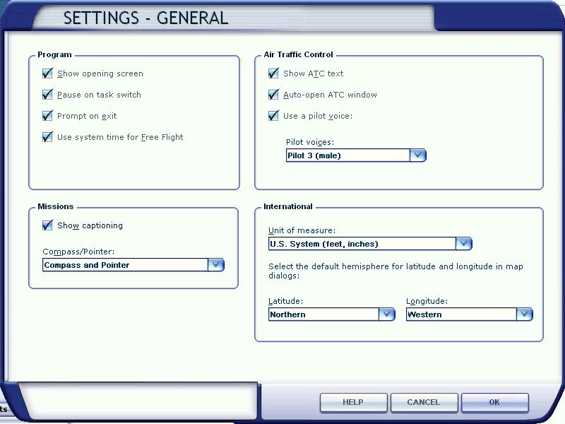
Ensure you have Flight Simulator up and running. First
click Settings, then General, then select the Show Captioning check
box, as shown below. This will ensure that you can both see the
dialog text as well as hear the sound file. By default, the Show
Captioning check box is left unchecked.
Assurez-vous
que les paramètres de FS sont corrects. Allez dans les
settings / Général et cocher Show Captioning. Ceci vous
assurera que les textes seront visibles et les fichiers sons
audibles. Par défaut, le Show Captioning est décoché
When you have done this, make sure the Allow realism
changes during Missions check box is selected - this will make
adding triggers and actions easier. Now click on the Mission
Creation Tutorial in the list of Missions, and then click Go To
Briefing. When the briefing document appears, click Fly!.
Then open up the Object Placement Tool.
Après
avoir fait ceci, assurez-vous que Allow Realism changes during
Missions est coché. Ceci permettra d'ajouter des déclencheurs
et des actions plus facilement.
The first thing that most missions will do is introduce the
mission to the user with some speech and text. The text will appear
on the screen the same time as the text is being rendered by the
audio system. The first step is to add the dialog actions. Do this by
clicking on Add, selecting Action in the First box, then DialogAction
in the Second box, and then enter the Text and SoundFileName
properties as appropriate:
La première
chose au début d'une mission est de faire une introduction en
texte et son. Le texte apparaîtra en même temps que le
son se jouera. Première étape, ajouter une boite de
dialogue. Cliquez sur Add, sélectionner Action dans la
première boite alors dans la seconde DialogAction et entrez
les propriétés de Text et SoundFileName
adéquat.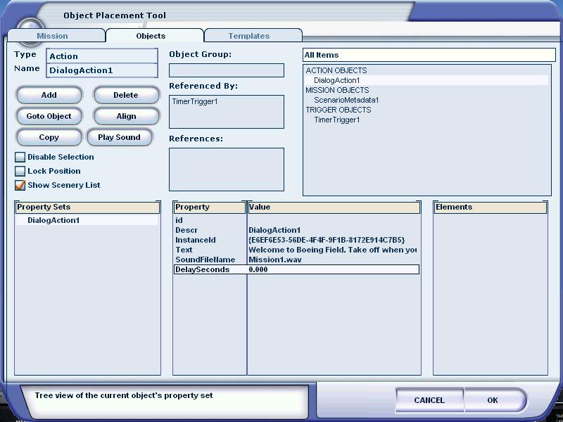
Repeat
this process of adding Dialog actions for all five recordings you
have made for this mission. In each case you should only be typing
into the Text and SoundFileName properties. Notice how each action is
appended with a number in the All Items list.
Répétez
ce processus pour tous les enregistrements que vous avez créez
pour la mission. Notez que chaque action est complétée
d'un numéro dans la liste All Items
The next step is to add a timer trigger, that will initiate the
first of our dialog actions.
L'étape
suivante consiste à ajouter des déclencheurs temporels
qui initialisera les actions de dialogue
To do this go to the Object tab of the tool, click Add, then
select Trigger from the First box, and TimerTrigger from the Second
box. Click Add again and you will see the list of properties
associated with a timer trigger:
Pour
ceci, allez sur l'onglet Object de l'outil, cliquez sur Add et
sélectionnez Trigger dans la première boite puis
TimerTrigger dans la seconde. Cliquez encore sur Add et vous verrez
la liste des propriétés associées au Déclencheur
temporel.
It
is best to let the user wait a few seconds before introducing the
mission to the user, so change the StopTime value to 5.0.
Leave the StartTime at 0.0, so the timer starts when the
flight is loaded. Actions are initiated by timer triggers when the
stop time is reached, so these two values will initiate the text and
speech 5 seconds into the mission.
Il
est bien de laisser quelques secondes a l'utilisateur avant de lancer
la mission, donc mettez la propriété StopTime à
5.0. Laissez StartTime à 0 ainsi le timer démarre quand
le vol commence. Les actions sont initialisées par le
déclencheur quand le temps est écoulé. Le texte
et le son seront donc traités 5 secondes après le début
de la mission
The property OneShot set to True simply means that the action
should only be fired once (this is not very important for timer
triggers, which are only fired once, but you will have to decide with
other triggers whether you want them to keep firing their actions if
a user keeps triggering them). Activated should be True - this means
that this trigger is to be considered active, and is not waiting for
any other event before it is to become active. Leave the other
properties as they are.
La propriété
OneShot est à True pour spécifier que cette action ne
s'exécutera que seule fois (ceci n'est pas très
important ppour un déclencheur temporel mais pour d'autres
types de déclenchements cela poeut être très
utile). Activated doit être à vrai. Ce qui permet de
considérer le déclencheur comme actif. et il n'y a pas
d'attente pour aucun autre événement avant qu'il le
devienne. Laissez les autre propriétés comme elles
sont.
We have not finished yet, as we have not yet linked the timer trigger
and the dialog action. Do this by clicking on Property Set
for the Actions property. This will bring up a list of items in the
Elements box that this trigger could be linked to. Double
click on DialogAction1 in the Elements box to link the trigger
and action. This will be shown both by a + sign appended to the
name in the Elements box, and also an entry in the References box, as
shown below:
Nous n'avons pas encore
fini. Nous n'avons pas encore liés les déclencheurs et
les dialogues. Pour ceci, cliquez sur Property Set dans la ligne
Actions de la liste Property. Cela fait apparaître une liste
d'item dans la boite éléments pouvant être liés.
Double-cliquez sur DialogAction1 pour liés les deux. Un signe
plus apparait devant le nom dans la boite Elements et aussi une
entrée dans la boite References comme ci-dessous
This
is all we need to do to introduce our mission.
C'est
tout pour l'introduction de la mission !!! (c'est déjà
pas mal)
Go back to the Missions tab and save off
the mission. Then exit the flight start the mission again, wait
five seconds, and you should both see and hear the text Welcome
to Boeing Field Take off when you are ready. If you do, then all
is well, if not, go back and check the properties for the trigger and
action.
Retourner dans l'onglet Missions
et sauvegardez la mission. Démarrer la misson, attendez 5
secondes, vous devriez voir et entendre la premier texte. Génial
non ? (avis du traducteur) si ce n'est pas le cas, retournez
contrôler les objets, propriétés et déclencheurs
(bon courage)
This is one of the most simple examples of a trigger and action,
but this process of linking these two elements of a mission applies
the tool.
Ceci est le plus simple exemple
de trigger et d'action possible mais le processus de lien entre deux
éléments de la mission s'applique dans tout l'outil
If it is not still loaded, reload the mission and open up the
Object Placement Tool.
Si ce n'est déjà
fait, rechargez la mission et ouvrez l'outil Object Placement
Tool
All our mission does so far is ask the user to
take off. To give them the next stage in the mission, we can give
them some more details just after the aircraft has taken off. To do
this we can use a property trigger and link it to our second dialog
action.
Notre mission fait plus que
demander à l'utilisateur de décoller. Pour give them
l'étape suivante dans la mission, nous devons donner un peu
plus de détails après que l'avion ait décollé.
Pour ceci, nous pouvons utiliser la propriété trigger
et la lié à la seconde boite de dialogue action.
Click Add, then select Trigger and PropertyTrigger. A
property trigger is one that tests one or more conditions, typically
speed or altitude of the aircraft, but there are many hundreds of
other possibilities.
Cliquez dur Add,
sélectionnez Trigger et Property/Trigger. La propriété
Trigger est là pour tester une ou plusieurs conditions.
Typiquement la vitesse ou l'altitude de l'avion mais aussi plusieurs
centaines d'autres possibilités.
In the Properties box of the property trigger, ensure
Activated is True, and click on the Property Set for Actions. Then
double click on DialogAction2 (in the Elements list) to link it to
the property trigger. Then double click on the Property Set for the
Condition property. This will bring up the Conditional Editor dialog
box. Click Add Term and select Simvar.AltitudeAMSL for the left hand
side of the condition (LHS). Leave the Operator as Greater Than, and
type 50.0 for the right hand side (RHS), so the dialog looks
like this:
Dans la boite propriétés
des propriétés du Trigger, vérifiez que
Activated est à True et cliquez sur la propriété
Set for Actions. Alors double-cliquez sur DialogAction2 (dans la
liste Elements) pour le lier à la propriété
Trigger. ensuite double-cliquez sur la propriété Set
for the Condition. Ceci affichera la boite de dialogue de l'éditeur
de conditions. Cliquez sur Add Term et sélectionnez
Simvar.AltitudeAMSL sur la gauche (LHS:) Laissez l'opératuer
plus grand que (GreaterThan) et tapez 50.0 dans le champ à
droite comme ci-après.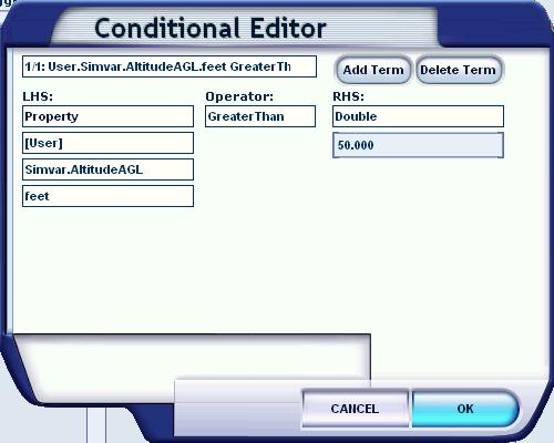
The
simple condition we have entered indicates that the trigger will be
fired when the user's aircraft is more than 50 feet above ground
level. The units of a condition appear under the Simvar property. If
the unit of measurement for any simulation variable is not obvious,
refer to the Simulation
Variables document. Click OK to add the condition to the trigger.
La simple condition que nous avons
entrée indique que le déclencheur s'activera quand
l'avion aura atteint 50 pieds au dessus du sol. Les unités de
la condition apparaissent sous la propriété Simvar. Si
l'unité de mesure pour une variable de simulation n'a pas
visible, allez voir le document Simultation Variables. Click OK pour
ajouter la condition au déclencheur.
For reference, the PropertyTrigger2 properties should now look
like this:
Pour faire un point, la
propriété PropertyTrigger2 doit présenter ceci
:
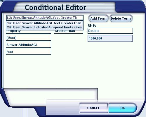
In
our sample mission we want the user to fly up to an altitude of 1000
feet, with a minimum speed of 80 knots, before returning. To do this
we should now enter a second property trigger, this time with two
conditions, and of course a link to the third speech dialog to
indicate when this has been done.
Dans
notre exemple, nous voulons que le pilote monte jusqu'a 1000 pieds à
la vitesse minimale de 80 noeuds avant de revenir. Pour ceci alors
allons saisir un second déclencheur, cette fois nous aurons
deux conditions et bien sur nous ferons la liaison avec la boite de
dialogue indiquant que ceci à été fait.
Enter
two conditions into the property editor:
Entrez
deux conditions dans l'éditeur de propriétés
Simvar.AltitudeAMSL Greater Than 1000.0
Simvar.IndicatedAirspeed Greater Than 80.0
And click on the Actions Property Set to link to DialogAction3.
Et
cliquez sur la propriété Actions pour lié à
DialogAction3
Save
off the mission, then restart it and test that both property trigger
dialog actions are triggered at the appropriate points. Notice how
simply climbing above 1000 feet does not fire the second property
trigger, it is necessary to increase the speed to 80 knots before it
does fire.
Sauvegardez la mission et
relancez la et testez si les deux trigger fonctionnent correctement.
Notez qu'il ne suffit pas de monter à 1000 pieds mais aussi
d'avoir une vitesse d'au moins 80 noeuds.
A proximity trigger will fire if the specified object (usually the
user's aircraft) enters a specified box. The box is defined by a
length, width and height, and can be placed anywhere in the world. It
is usually most useful to move to the approximate location for the
proximity trigger first. The joystick and hat switch can be used to
move the cross hairs, you may also want to use the Slew feature to
move larger distances. In our example we want to create a proximity
trigger at the ideal landing spot on the runway (the runway number).
First use the joystick to select the center of the runway number,
then click Add and select AreaDefinition and RectangleArea. The
length, width and height property values can be edited, so change
them to a length and width of 100 (units are in meters), and a height
of 20.
Un trigger (déclencheur) de
proximité s'activera si l'objet spécifié
(habituellement l'avion) entre dans un volume spécifié.
Le volume est défini par la longueur, largeur et hauteur et
peut être placé n'importe où dans le monde. Il
est souvent utilisé pour se déplacé vers un
endroit précis. Le joystick et le chapeau peut être
utilisés to move the cross hairs, vous pourrez aussi couloir
utiliser le mode déplacment pour l'emmener sur des longues
distances. Dans notre exemple nous vouons créer un trigger à
proximité sur point idéal d'atterissage (le numéro
de la piste). Premièrement utilisez le joystick pour pointer
sur le centre de la piste et cliquez sur Add et sélectionnez
AreaDefinition et RectangleArea. La longueur, largeur et la hauteur
peut être éditée. Mettez 100 pour la longueur et
la largeur et 20 pour la hauteur. 
The
orientation about each axis can also be changed (though is not
necessary in this case), and set the Rendered property to True if the
box should actually appear in view. Set Rendered to be True for this
sample.
L'orientation sur chaque axe peut
être peut être changé (ce n'est pas nécessaire
dans notre cas) et positionnez la propriété Rendered à
True si la boite doit actuellement apparaitre dans la vue. Mettre
Rendered à True pour cette exemple
The next
step is to add the proximity trigger and attach it to this area
definition. To do this select Add then select Trigger and
ProximityTrigger, then in the Properties box click on Areas, then
double click RectangularArea1 in the Elements box. This links the
trigger to the area. Also, select the OnEnterActions property and
link it to DialogAction4, to link entering the area with the
appropriate speech.
L'étape
suivante consiste à ajouter un trigger de proximité et
d'attacher celui-ci au volume défini. Pour faire ceci,
sélectionnez Add puis Trigger et Proximity/Trigger, alors dans
la boite Properties box cliquez sur Areas, double-cliquez
RectangularArea1 dans la boite Elements. Ceci lie le trigger au
volume. Ensuite, sélectionnez la propriété
OnEnterActions et l'associé à DialogAction4 pour lié
l'entrée dans la zone au texte approprié
For
this proximity trigger we do not want it to be activated until the
user is airborne, and has completed the previous step (climbed to
1000ft with a speed of 80 knots), so we set the Activated property to
False. The next step is to change the activated property to true, at
the appropriate time.
Pour ce trigger de
proximité, nous n'avons ne voulons pas qu'il soit actif tant
que l'utilisateur est en l'air et ait réaliser l'étape
précédent (montée 1000 pieds et vitesse 80
noeuds). Pour cela, nou avons positionné la propriété
Activated à False. L'étape suivante est de changer la
propriété Activated à True le moment venu
To link the inactive proximity trigger to the completion of a
previous action, go through the following steps.
Pour
lié un déclencheur de proximité inactif a la
réalisation de l'action précédente, réalisez
les opérations suivantes:
First, add an
ObjectActivationAction to the mission. It only requires a few
properties: leave NewObjectState as True, and click on
ObjectReferenceList to display a list in the Elements box. Double
click on ProximityTrigger4. This means when the object
activation action occurs it will activate the proximity
trigger.
Premièrement, ajoutez un
object ObjectActivationAction à la mission. Il demande
quelques propriétés. Laissez NewObjectState as True et
cliquez sur ObjectReferenceList pour afficher dans la liste Elements.
Double-cliquez sur ProximityTrigger4. Ceci permet quand l'activation
de l'objet apparaît que le déclencheur de proximité
s'active.
Next, select PropertyTrigger3 (with the
altitude of 1000 feet and speed of 80 knots condition) from the All
Items list, and click on Actions. Double click on the
ObjectActivationAction5 entry under Elements. PropertyTrigger3 now
fires two actions, a dialog action and the object activation
action.
Ensuite, sélectionnez
PropertyTrigger3 (avec les conditions altitude = 1000 et vitesse =
80) dans la liste All items et cliquez sur Actions. Double-cliquez
sur l'entrée ObjectActivationAction5 sous Elements.
ProperyTriiger3 réalisera maintenant deux actions, le
déclenchement du dialogue et l'activation de l'objet
The
logic here should be fairly clear. The proximity trigger is inactive
until the user's aircraft reaches the required altitude and speed.
When the aircraft does meet these requirements the proximity trigger
becomes active.
La logique ici est
relativement claire. Le déclencheur de proximité est
inactif tant que l'utilisateur n'a pas atteint l'altitude et la
vitesse requise. Quand l'avion aura atteint les critères
altitudes/vitesse le déclencheur devriendra actif.
Many missions will end with a successful landing. Add an
AirportLandingTrigger and enter the four digit Airport identification
code to identify the correct airport (KSEA for SeatTac International
or KBFI for Boeing Field, for example). Again set the Activated
property to False. Set the Actions property to trigger DialogAction5,
which is the appropriate mission completed text. For this case leave
the landing as FullStop (the alternatives are TouchDown and Any), and
leave the RunwayFilter entry for now (it is possible to specify which
runway must be landed on to fire the trigger).
Beaucoup
de missions se terminent par un atterissage. Ajouter un objet
AirportLandingTrigger et entrez les quatres lettres d'identification
(KSEA pour SeaTac Internation ou KBFI pour Boeing Field). Placez
encore la propriété Activated à False. Associés
la propriété Actions du déclencheur à
DialogAction5 qui annoncera la fin de la mission. Dans cet exemple,
laissez landing à FullStop (les autres possibilités
sont TouchDown et Any) et laissez l'entrée RunwayFilter sur
Now (il est possible de spécifier sur quelle piste atterir
pour activer le déclencheur)
Go back to the
ObjectActivationAction created in Step 9 (click on it in the All
Items list) and add the AirportLandingTrigger to the actions that
become active when the object activation action fires.
Retourner
sur ObjectActivationAction créer à l'étape 9
(cliquez dessus dans la liste All Items) et ajouter
AirportLandingTrigger dans les actions il deviendra actif quand
l'objet activaation sera déclenché
For this mission we might decide that there are two goals, one
for the user to enter the proximity trigger box and land on the
painted runway number, and the second for a correct landing (coming
to a complete stop).
Add goals by clicking Add, then
selecting Goal. The goal state should be left as pending. The text
entered here will appear in the End Mission dialog, along with the
final state of the goal (pending, completed, or failed). Enter
two goals, one for landing on the runway number, and another for a
correct landing. The text can be Landed on the Painted Number ,
with an Order number of 1, for the first goal, and Complete Stop,
with an Order number of 2, for the second goal.
Next, add a
GoalResolutionAction for each goal. The Goals property of this action
should be linked in the usual way to the goals themselves. Go to the
ProximityTrigger and add the second goal resolution action (Landed on
the Painted Number) to its list of actions. Finally go back to the
AirportLandingTrigger and add the correct goal resolution action
(Complete Stop) to the list of actions which it fires.
There
is currently no concept of an optional goal in the Mission
system.
Rewards are different from goals, they are persistent and added to the user's pilot records. A reward can be serious in the sense of a certificate for achieving some level of skill, or more trivial, for example a reward for photographing a humpback whale off Hawaii. The rewards that ship with Flight Simulator are integrated into the missions and tutorials that are provided, so it makes most sense to create your own rewards, if you choose to use them.
To create the simplest form of reward, go through the following steps:
Create artwork for the reward. Use appropriate art tools to create one detailed piece of art for the reward (300 pixels wide by 370 pixels in height) and one thumbnail piece of art (100 pixels wide by 80 pixels in height). These will be referenced by the reward file and appear on the user's screen when aiming at and achieving the reward. The artwork can be .bmp or .jpg files.
Fill out an xml file that matches the following format.
|
<?xml
version="1.0" encoding="ISO-8859-1" ?>
|
Create and enter a GUID for the reward, to be referenced by the mission itself.
Enter a name to appear in Flight Simulator X.
Enter a description to appear when the user selects View details.
Enter a type for the reward, which can be one of: TROPHY, BADGE, MEDAL, CERTIFICATE, POSTCARD or SPECIAL_ITEM.
Enter the filename for the thumbnail piece of art, and the detailed piece of art.
Ensure that both pieces of art and the xml file are in the same folder, then run the command line tool, BGLComp with the xml file as input (entering the command: BGLComp reward.xml). Alternatively drag the reward xml file over the BGLComp icon. The BGLComp tool is in the SDK\Environment Kit\BGLComp SDK folder. This will create a rewards file, with a .rwd extension. Copy the rewards file to the Microsoft Flight Simulator X/rewards folder. This file includes the artwork, so is the only file required.
Add the reward to a mission by selecting its GUID in a Grant Reward action, and then link this action it to the final trigger.
A rewards file can contain any number of rewards, simply by entering as many <Reward> </Reward> entries in the xml file as there are rewards. More complex rewards can be created by adding a <Criteria> section to a reward. The following table shows an example with all the possible criteria.
|
<! An example comment: hours include decimal places, 2.5 hours for example >
<Criteria
landings="2" differentAirports="2"> |
The criteria in the above example are not very realistic, they require the user to have completed two landings at two different airports and landed at the list of the three specified (KORD, KSEA, and KBFI). It also requires 10 hours experience in a whole range of situations, and that two other rewards must have been earned before this one can be given. All criteria are logically ANDed to make up the requirement for a reward, and all equals signs should be interpreted as greater than or equal to (in other words, at least 10 hours experience in all the aicraft and situations listed in the example above). The following table gives some more realistic examples:
|
<Reward
rewardId="{GUID}" name="10 hours flying "
description="Earn a medal for flying any aircraft for a
total of 10 hours flying time." type="MEDAL"
bitmap="small.jpg"
rewardDetailBitmap="large.jpg"> |
|
<Reward
rewardId="{GUID}" name="15 hours at night "
description="Earn a certificate for flying any aircraft
for a total of 15 hours flying at night."
type="CERTIFICATE" bitmap="small.jpg"
rewardDetailBitmap="large.jpg"> |
|
<Reward
rewardId="{GUID}" name="25 landings"
description="Earn a badge for completing 25 landings."
type="BADGE" bitmap="small.jpg"
rewardDetailBitmap="large.jpg"> |
|
<Reward
rewardId="{GUID}" name="Remote location"
description="Earn a postcard for landing on Easter
Island." type="POSTCARD" bitmap="small.jpg"
rewardDetailBitmap="large.jpg"> |
|
<Reward
rewardId="{GUID}" name="Busy airports "
description="Earn a trophy for landing at 3 of the busiest
airports in the world: London Heathrow, Atlanta and Singapore."
type="TROPHY" bitmap="small.jpg"
rewardDetailBitmap="large.jpg"> |
Having completed building the mission, ensure you have saved it
all off, and then test it thoroughly. The best designed mission can
still exhibit strange behaviour during testing.
There are of
course many cases where the mission might inappropriately reward a
user. For example, the proximity trigger in our example will still
fire correctly if the aircraft is landing upside down, without its
gear down, too fast, or whatever. To tighten up a mission you will
need to add conditions to many of the triggers, especially the
proximity triggers.
This ends the tutorial section of this
document. The most popular and useful actions and triggers are
covered in the tutorial, but there are many others, and the following
reference section describes all the Mission Objects.
You can also refer to the missions provided with Flight Simulator (by loading them into the Object Placement Tool, or viewing the XML in an appropriate editor) for examples of how different triggers, actions, goals and rewards can be used. Mission files created using this tool are in an open XML format. Mission files supplied with Flight Simulator X are in a binary format with the .SPB extension. If both are present in the same folder, the .SPB file is read in preference. To help in the understanding of the mission system, the XML files used to create the default missions are supplied in a sub-folder of this SDK.
Mission files can either be in XML or SPB (Sim-Prop Binary) format. The binary format is faster to load that its XML equivalent. To create an SPB file, run the simpropcompiler.exe tool, which is in the SDK\Core Utiliites Kit\SimProp folder. This is a command-line tool, so open a command window, navigate to the SDK\Core Utiliites Kit\SimProp folder, then enter the following command:
> Simpropcompiler 2spb –symbols C:\Program
Files\Microsoft Games\Microsoft Flight Simulator X\propdefs\*.xml
yourMission.xml yourMission.spb
Note that file extensions are required for both the input and output filenames. To simply validate the xml file without creating any output file, change the keyword 2spb to validate.
To get more detailed error reports when there is an error in a mission file, make sure the following entry is in the fsx.cfg file, which is in the Documents and Settings\<username>\Application Data\Microsoft\FSX folder.
[DEBUG]
ReportLoadErrors=1
This section contains a reference of all the properties that apply to each of the Mission Objects.
An action is a declarative way to cause something to happen in the world. Examples of actions are playing a sound file, completing an objective, showing text in the adventure window, failing an engine, completing a goal, etc.
All actions include the following properties.
|
Property |
Description |
|
id |
Reserved. Do not edit this field. |
|
Descr |
The name of the action. The system will generate a name such as DialogAction1, simply be appending the number of the next action to the type of action. This name can be edited to help identifiy it further. Make sure though that the name is unique. |
|
InstanceId |
This is the GUID generated to ensure the object has a unique reference. Do not edit this field |
Waypoints are essential for the
movement of certain AI objects. The activate waypoints action
provides one or more AI object with a new list of waypoints.
|
Property |
Description |
|
See description above. |
|
|
ObjectReference |
List of one or more AI objects that are to use the new waypoint list. |
|
WaypointList |
List of one or more waypoints that are to become active. |
An adjust payload action is used to set, or add to, the weight
on a payload station.
|
Property |
Description |
|
See description above. |
|
|
ObjectReference |
The list of objects to which the payload adjustment applies. |
|
StationIndex |
The index number of the station. |
|
AdjustmentType |
One of: Set or Add. |
|
Weight |
The quantitiy of the adjustment. |
|
Units |
One of: number, feet, g_force, knots, pounds, percent, boolean, degrees or radians. |
An attach droppable payload action is used to change the
payload that gets dropped when the user presses a key configured to
drop the payload.
|
Property |
Description |
|
See description above. |
|
|
PayloadName |
The name of the container that becomes the object to be dropped. |
|
PayloadCount |
The number of the payload objects that should be attached. |
|
ObjectReferenceList |
The objects which are each to get the assigned payload. |
The attach effect action attaches a single special effect
(such as smoke, fire, contrail etc.) to one or more objects.
|
Property |
Description |
|
See description above. |
|
|
EffectName |
Filename of special effect. |
|
AttachPointName |
The name of the attach point (physical location) of where the effect is to be applied. See the Modeling Tools documentation for information on attach points. |
|
ObjectReferenceList |
List of objects that the effect applies to. |
A change object type action changes the object the user is in.
For example, it can be used to change from one type of aircraft to
another.
|
Property |
Description |
|
See description above. |
|
|
ObjectType |
The ID of the new object. |
A count action will add the value of the Count property to the list of triggers (which should be Counter triggers). Counter triggers will fire when a certain specified count is reached.
|
Property |
Description |
|
See description above. |
|
|
Count |
Value to be added to the Counter triggers current counter. |
|
Triggers |
List of Counter triggers to have their counts incremented. Note that these must be counter triggers, even though the Object Placement Tool lists other trigger types. |
A custom action is used to enable communications between a mission and a SimConnect client application.
|
Property |
Description |
|
See description above. |
|
|
PayloadString |
Text that will be transmitted to the SimConnect client when the action is initiated. The text can be any string that the client might find useful. |
|
WaitForCompletion |
Set this to True if a completion message must be received from the SimConnect client, before the mission progresses. Set to False otherwise. |
A dialog action is used to add speech to be rendered over the audio system, and/or text to be displayed on the screen. See the explanation in the tutorial for an example.
|
Property |
Description |
|
See description above. |
|
|
Text |
The text to appear on the screen. Can be left blank. |
|
SoundFileName |
The wave file to be rendered by the audio system. The file should be in the \sounds directory of the mission. Can be left blank. |
|
DelaySeconds |
A delay in seconds after the text and audio are rendered. Can be used to allow time for the user to respond to the dialog, before performing another action. |
A failure action is used to change the behavior of one of the
aircraft's systems. It is possible also to change a failing system's
status back to fully functional, by changing its HealthPercent value
to 100. Failures only apply to the user aircraft.
|
Property |
Description |
|
See description above. |
|
|
System |
One of: Engine, EngineFire, Coolant, OilSystem, OilLeak, VacuumSystem, Pitot, Static, ElectricalSystem, Generator, FuelPump, FuelLeak, APU, APUFire, TurbineIgnition, HydraulicPump, HydraulicLeak, LeftMagneto, RightMagneto, Elevator, LeftAileron, RightAileron, Rudder, RearTail, LeftFlap, RightFlap, LeftWing, LeftWingTip, RightWing, RightWingTip, CenterGear, RightGear, LeftGear, AuxGear, LeftBrake, RightBrake, BrakeSystemHydraulicSource, AltitudeIndicator, AirspeedIndicator, Altimeter, DirectionalGyro, Compass, TurnCoordinator, VSI, ComRadios, NavRadios, ADFRadios, or Transponder. |
|
SystemIndex |
If an aircraft has multiple systems (usually applies to engines), enter the index of the system that the failure should apply to. |
|
Behavior |
One of: Failed, Failing, Burn or Leak. |
|
HealthPercent |
Enter a value of between 0 (complete failure) and 100 (fully functional). |
The goal resolution action is used to set whether goals have
been completed or not. See the explanation
in the tutorial for an example.
|
Property |
Description |
|
See description above. |
|
|
GoalResolution |
Set to completed or failed. |
|
Goals |
List of Goal Objects to have their resolution changed. |
The grant reward action rewards the user with a single reward,
to be placed in their pilot records. See Creating
Rewards for more details.
|
Property |
Description |
|
See description above. |
|
|
RewardRef |
GUID of the appropriate reward. |
The object activation action will change the state of most different types of object, Triggers, AI objects, Scenery objects and some Mission objects. Do not use it for points of interest, use PointOfInterestActivationAction for that particular case.
|
Property |
Description |
|
See description above. |
|
|
NewObjectState |
Set to True or False. |
|
ObjectReferenceList |
List of objects (AI Object, Scenery, Mission Objects and Triggers) to have their status changed. |
The one shot sound action will render a single wave file. Use
this for sound effects rather than dialog (use the Dialog
action for speech audio).
|
Property |
Description |
|
See description above. |
|
|
SoundFileName |
The wave file to be rendered. The file should be in the \sounds directory of the mission. |
The play animation action will initiate an animation sequence
on one or more objects.
|
Property |
Description |
|
See description above. |
|
|
AnimationGUID |
GUID of the animation. |
|
LoopAnimation |
Set to True to loop the animation. |
|
ObjectReferenceList |
The list of objects that the animation is to apply to. |
The play list action will play the specified music items on the adventure music track. Individual play list items can be set to a random position within the play list.
|
Property |
Description |
|
See description above. |
|
|
PlayListItem |
Play list item object. To enter a play list, double click on the PlayListItem Property Set, this will bring up an Objects dialog and select New, Insert Before or Insert After to add items to the list. Click OK when there are enough items in the list. This list will then appear in the Property Sets box of the Objects tab. Clicking on any one of these items will bring up the properties for each item. |
A playlist item is an audio track that forms part of a playlist action.
|
Property |
Description |
|
id |
Reserved. Do not edit this property. |
|
Descr |
The name of the item. The system will generate a name such as PlayListItem1. This name can be edited to help identifiy it further. Make sure though that the name is unique. |
|
SoundFileName |
The name of the wave file (typically music track) to be played. |
|
RandomizeInList |
Set to True to randomize the playing of this particular track in the playlist. |
A point of interest activation action will change the state of one or more Point of Interest objects. It is very similar to ObjectActivationAction, but also sets the current point of interest to be the one with the lowest cycle order in its list.
|
Property |
Description |
|
See description above. |
|
|
NewObjectState |
Set to True or False. |
|
ObjectReferenceList |
List of one or more Point of Interest objects to have their status changed. |
The random action is used to initiate one action from a list
of possibilites.
|
Property |
Description |
|
See description above. |
|
|
ProbabilityPercent |
The probablity that any action at all will fire. Enter 100 to ensure an action will fire. |
|
Actions |
List of actions from which one is chosen at random. |
The reset timer action is used to set the current time of a
list of timers back to their start times.
|
Property |
Description |
|
See description above. |
|
|
Triggers |
List of Timer Triggers to be reset. |
The rumble action is used to initiate rumble in the Universal Controller (typically an XBox controller).
|
Property |
Description |
|
See description above. |
|
|
Intensity |
One of: Off, Low, Med, High |
|
Duration |
Duration of the rumble in seconds, or fraction of a second. |
A spawn action will create all the new objects (including AI aircraft, scenery, actions and triggers) specified in a Spawn List object. A spawn action that is called mutliple times will create multiple objects.
|
Property |
Description |
|
See description above. |
|
|
SpawnLists |
List of one or more Spawn List objects. |
The timer adjust action adds the DeltaTime property value to the timer trigger's internal clock.
|
Property |
Description |
|
See description above. |
|
|
DeltaTime |
A positive or negative timer adjustment, in seconds. |
|
Triggers |
List of Timer Triggers to have the timer adjustment. |
AI objects are computer controlled vehicles. Four types of vehicle can be controlled by the AI (artificial intelligence) component of Flight Simulator:
Aircraft
Boats
Ground vehicles
Other
AI objects appear under the title PATH_CONTAINER_OBJECTS in the All Items list. If an AI controlled object is added to the mission, the following properties apply to it:
|
Property |
Description |
|
Descr |
The name of the object. The system will generate a name such as Aircraft1 or Ferry1, simply be appending the number of the next object to the type of the object. This name can be edited to help identifiy it further. Make sure though that the name is unique. |
|
InstanceId |
This is the GUID generated to ensure the object has a unique reference. Do not edit this field |
|
ContainerTitle |
The make and model of the aircraft, or type of boat or vehicle. This is the title that is listed in the Aircraft Configuration File. |
|
ContainerID |
An ID number given to this object. This can be used by ChangeObjectTypeAction to change, for example, the user's aircraft from one type to another. |
|
IsOnGround |
Set to True or False. |
|
WorldPosition |
Latitude, longitude, and altitude in feet. For example: |
|
Orientation |
Heading, Pitch and Bank. |
|
EngineStarted |
True or False. |
|
IdentificationNumbers |
An aircraft identifcation number such as NAA000. Not used for ground vehicles or boats. |
|
AIType |
One of: None, Airplane, Helicopter,
WanderBoat, GoundVehicle, FuelTruck,
BaggageCart, BaggageLoader, or AirportAmbient. |
|
GroundVehicleAI |
If the AIType is GroundVehicle then clicking on this entry will initiate a GroundVehicleAI object. Expand the entry in the Property Sets box to expose the new objects. |
|
AircraftAI |
If the AIType is Airplane then clicking on this entry will initiate an AircraftAI object. Expand the entry in the Property Sets box to expose the new objects. |
|
Activated |
Set to True or False. This can be changed during a mission using the Object Activation action. |
|
MDLGuid |
Optional. If a model GUID is entered here, it will override the models referenced in the aircraft model.cfg file. |
|
LabelMode |
One of: UserDefined, On, or Off. If UserDefined is set, the label format will be taken from the user settings in the Settings - Display/Traffic dialog. |
AircraftAI objects are referenced by AI
Objects.
|
Property |
Description |
|
Unit_Mode |
One of: Sleep, Zombie, Waypoint, Takeoff, Landing, Taxi, Working, Waiting |
|
GroundCruiseSpeed |
Ground speed in knots. |
|
GroundTurnSpeed |
Turning speed in knots. |
|
GroundTurnTime |
Time in seconds to make a 90 degree turn. A recommended minimum turn time is 0.5 seconds. |
|
WaypointList |
|
|
Schedule |
Used internally only, for saving flight/mission information. |
|
TakeofAI |
Provide this object only if the AircraftAIState is set to SIMPLE_TAKEOFF. |
|
LandingAI |
Provide this object only if the AircraftAIState is set to SIMPLE_LANDING. |
|
TaxiAI |
Provide this object only if the AircraftAIState is set to SIMPLE_TAXI. |
|
ICAOIdent |
Airport ID, such as PAFA. |
|
AircraftAIState |
One of: SIMPLE_FLIGHT, SIMPLE_TAXI, SIMPLE_LANDING, or SIMPLE_TAKEOFF. |
|
MaxBank |
The maximum bank angle the aircraft should make, in degrees. |
|
WaypointTouchDistance |
The distance in meters from a waypoint that is acceptable as having reached the waypoint. |
|
PatternEntry |
One of: Downwind, Base, or Straight_In. |
Takeoff AI objects are referenced by AircraftAI
objects.
|
Property |
Description |
|
AITakeoffMode |
One of: None, Init, Start_Rolling, Rolling, or Airborne. |
Landing AI objects are referenced by AircraftAI objects.
|
Property |
Description |
|
InitialFlaps |
A value between 0.0 (for no flaps) and 1.0 (flaps fully extended). |
|
ThresholdLLA |
Latitude Longitude and Altitude in feet, of the splot that the
aircraft should try to land on. For example: |
|
RunwayLength |
|
|
RunwayAlt |
|
|
RunwayHeading |
|
|
ApproachSlope |
|
|
InitialAlt |
|
|
MaxInterceptAngle |
Taxi AI objects are referenced by AircraftAI
objects.
|
Property |
Description |
|
NextWaypoint |
The index in the taxi route of the next waypoint. |
|
CurrentWaypoint |
The index in the taxi route of the current waypoint. |
|
CurrentWaypointL |
Current waypoint latitude longitude and altitude in feet. |
|
PrevWaypoint |
The index in the taxi route of the previous waypoint, or -1 if there is no previous waypoint. |
|
Destination |
Destination latitude longitude and altitude in feet. |
|
HoldClearPoint |
|
|
HoldShortPoint |
|
|
HoldFlags |
|
|
HoldStartTime |
|
|
HasRunwayHeading |
|
|
RunwayHeading |
|
|
IsPushingBack |
|
|
PassOnComing |
|
Ground vehicle AI objects are for those land or sea vehicles which are to follow a course. The course is made up of a series of waypoints.
Ground vehicle AI objects are referenced by AI Objects.
|
Property |
Description |
|
GroundCruiseSpeed |
Ground speed in knots. |
|
GroundTurnSpeed |
Turning speed in knots. |
|
GroundTurnTime |
Time in seconds to make a 90 degree turn. A recommended minimum turn time is 0.5 seconds. |
|
WaypointList |
WaypointList object.Click on WaypointList in the Property Sets box to open up the properties for a WaypointList object. |
A waypoint list object contains a list of waypoints, and some
other general properties for the motion of the AI object.
Waypoint
list objects are referenced by Ground
vehicle AI objects, Aircraft AI
and MSOWaypointController
objects.
|
Property |
Description |
|
Waypoint |
List of one or more Waypoint objects. Click on this entry to open up the Object dialog to add individual waypoints. |
|
WrapWaypoints |
Set to True if, after reaching the last waypoint, the first waypoint should become the next in the list. |
|
CurrentWaypoint |
The index of the waypoint the AI object is currently aiming for. |
|
BackupToFirst |
Set to True if the aircraft should backup to the first waypoint. |
A waypoint is a location in the world, with a set speed, that
an AI object should aim for.
Waypoint objects are referenced by
Waypoint list objects.
|
Property |
Description |
|
Descr |
The name of the waypoint. The system will generate a name such as Waypoint1. This name can be edited to help identifiy it further. Make sure though that the name is unique. |
|
InstanceID |
This is the GUID generated to ensure the object has a unique reference. Do not edit this field |
|
SpeedKnots |
The desired speed in knots for the object when it passes the waypoint. |
|
WaypointID |
An ID number for the waypoint. |
|
WorldPosition |
Latitude, longitude, and altitude in feet. For example: |
|
AltitudeIsAGL |
Set to True if the alititude is above ground level, set to False if the altitude is above mean sea level. Note that the Align function of the tool does not preserve this setting correctly. |
Only one type of area definition is supported, RectangleArea, which defines a 3D box, and contains the following properties:
|
Property |
Descrption |
|
id |
Reserved. Do not edit this field. |
|
Descr |
The name of the object. The system will generate a name such as RectangleArea1, simply be appending the number of the next object to the type of the object. This name can be edited to help identifiy it further. Make sure though that the name is unique. |
|
InstanceId |
This is the GUID generated to ensure the object has a unique reference. Do not edit this field |
|
Length |
Length of the box in meters. |
|
Width |
Width of the box in meters. |
|
Height |
Height of the box in meters. |
|
Orientation |
Heading, Pitch and Bank, or orientations about the three axis, in degrees. |
|
Rendered |
Set to True if the bounding box is to be rendered on the screen. |
|
AttachedWorldPosition |
An optional Attached World Position object. This fixes the area definition to a specific point. Leave the AttachedWorldObject blank in this case. |
|
AttachedWorldObject |
An optional Attached World object. This enables the area definition to be attached to a moving object. Leave the AttachedWorldPosition blank in this case. |
A group object simply defines a single reference to one or more objects. This is helpful if a selection of object is used a number of times, however, group objects cannot refer to other group objects.
|
Property |
Description |
|
Descr |
The name of the group object. The system will generate a name such as Group1, simply be appending the number of the next group object the word Group. This name can be edited to help identifiy it further. Make sure though that the name is unique. |
|
WorldPosition |
Latitude, longitude, and altitude in feet. For example: |
|
GroupedObjects |
List of objects in the group. |
There are five types of Mission Object. Mission objects have the same generic properties as Actions.
Use the camera mission object to place a camera in the world,
which can be at a fixed location or attached to another (moving)
object. The view from the camera will become the main view for the
user.
|
Property |
Description |
|
See description above. |
|
|
Activated |
Set to True or False. This can be changed during a mission using the Object Activation action. |
|
AttachedWorldPosition |
An optional Attached World Position object. This fixes the camera to a specific point. Leave the AttachedWorldObject blank in this case. |
|
AttachedWorldObject |
An optional Attached World object. This enables the camera to be attached to a moving object. Leave the AttachedWorldPosition blank in this case. |
|
ObjectReference |
This object the camera is looking at. |
Attached world position objects are referenced by Area
definition objects, Camera
mission objects, Picture
in Picture view controller mission objects, and Point
of interest mission objects.
|
Property |
Description |
|
WorldPosition |
Latitude, longitude, and altitude in feet. For example: |
|
AltitudeIsAGL |
Set to True if the alititude is above ground level, set to False if the altitude is above mean sea level. |
Attached world objects are referenced by Area
definition objects, Camera
mission objects, Picture
in Picture view controller mission objects, and Point
of interest mission objects.
|
Property |
Description |
|
ObjectReference |
The object that is to be attached to. |
|
OffsetXYZ |
Four floating point values, containing an offset from the center of the ObjectReference object in the x,y and z directions. The fourth float is unused. |
A PictureInPictureViewController object adds a small view window and is typically used for a "bomb-cam" - giving a view of or from a falling object.
|
Property |
Description |
|
See description above. |
|
|
Condition |
Clicking on this will load up the Conditional Editor, to apply conditions to the activation of this mission object. |
|
UseTargetPosition |
Set to True or False. True indicates that the camera will try to keep the AttachedWorldObject, if one is set, in view. |
|
AttachedWorldPosition |
An optional Attached World Position object.This fixes the view controller to a specific point. Leave the AttachedWorldObject blank in this case. |
|
AttachedWorldObjects |
An optional Attached World object. This enables the view controller to be attached to a moving object. Leave the AttachedWorldPosition blank in this case. |
|
Activated |
Set to True or False. This can be changed during a mission using the Object Activation action. |
|
ViewCloseDelay |
A delay in seconds that will occur before the camera shuts down, in the event that the AttachedWorldObject, if one is set, is removed. |
|
CameraDistance |
The distance in meters the camera is away from the AttachedWorldObject, if one is set. |
|
CameraOffsetY |
The height in meters the camera is away from the AttachedWorldObject, if one is set. |
|
CameraPitch |
The angle in degrees that the camera is facing. A negtive value indicating a downward view. |
Use the point of interest object to highlight a location or other object. The highlight can be, for example, a vertical beam of light pointing at the object. Points of interest are displayed in the mission compass, and can be stepped through according to the cycle order.
|
Property |
Description |
|
See description above. |
|
|
Activated |
Set to True or False. This can be changed during a mission using the Point of Interest Activation action. |
|
SelectedModelGuid |
GUID of the model displayed in the scene when the point of interest is selected in the compass. This can be a vertical beam of light, or another suitable object highlighting model. |
|
UnselectedModelGuid |
GUID of the model displayed in the scene when the point of interest is not selected in the mission compass. A zero GUID will cause nothing to be rendered, which is the default. |
|
CurrentSelection |
Set to True if you want this object to be the current selection when the mission starts. |
|
CycleOrder |
The cycle order is the order in which points of interest are cycled in the mission compass, the lowest number first. |
|
TargetName |
The name that is to appear on the mission compass when the object is selected in it. |
|
MinimumModelScale |
The scale factor to be applied when the object is MinimumScaleDistance away from the view camera. |
|
MinimumScaleDistance |
If the object is closer than the MinimumScaleDistance to the view camera, it will be scaled by MinimumModelScale. |
|
MaximumModelScale |
Scale factor to be applied when the object is MaximumScaleDistance away from the view camera. |
|
MaximumScaleDistance |
The distance beyond which the object is scales by MaximumModelScale. |
|
AttachedWorldPosition |
An optional Attached World Position object.This fixes the highlight pointer to a specific point. Leave the AttachedWorldObject blank in this case. |
|
AttachedWorldObject |
An optional Attached World object.This enables the highlight pointer to be attached to a moving object. Leave the AttachedWorldPosition blank in this case. |
This object can be used to override the user's realism settings. For the specific properties: User Specified indicates that the user's settings should be used.
|
Property |
Description |
|
See description above. Note that RealismOverrides objects do not have an InstanceID. |
|
|
FlyingTips |
One of: User Specified, Enable, or Disable. |
|
CrashBehavior |
One of: User Specified, AutoRecover, ResetFlight or EndFlight. |
|
FlightRealism |
One of: User Specified, Enforced, or Relaxed. |
|
ATCMenuDisabled |
Set to True to disable the ATC menu. |
|
UnlimitedFuel |
One of: User Specified, Limited, or Unlimited. |
|
AircraftLabels |
One of: User Specified, Enabled, or Disabled. |
A RidgeLift object is used to simulate the effect of a hill slope on the wind.
|
|
|
Property |
Description |
|
See description above. Note that RealismOverrides objects do not have an InstanceID. |
|
|
Activated |
Set to True or False. This can be changed during a mission using the Object Activation action. |
|
ObjectReference |
A reference to an AreaDefinition object that defines a box that is the bounding area of the ridge lift. It is very important that the heading setting of the AreaDefinition points in the same direction as the slope (to the left in the above diagram). |
|
AirObjectModelGuid |
An optional model GUID. The model will be rendered within the ridge lift box. |
|
ScaleModel |
Set to True to if the model should be scaled to match the size of the ridge lift box. Set to False to render the model to its own scale. |
|
CoreRateScalar |
A scalar value that is applied to the wind in the Core area of the ridge lift. A positive value will provide an updraft, a negative value a downdraft. Typically a positive value such as 0.5 would be entered here. So if the wind speed was 8 m/s, an updraft of 4 m/s would be applied. |
|
CoreTurbulence |
A variation scalar that is applied to the wind speed. For example, if a value of 0.1 is entered, and the wind speed is 8 m/s, the wind speed in the ridge lift Core area will be randomly varying between 7.2 and 8.8 m/s. |
|
SinkRateScalar |
A scalar value that is applied to the wind in the Sink area of the ridge lift. A positive value will provide an updraft, a negative value a downdraft. Typically a negative value such as 0.5 would be entered here. So if the wind speed was 8 m/s, an downdraft of 4 m/s would be applied. |
|
SinkTurbulence |
A variation scalar that is applied to the wind speed. For example, if a value of 0.1 is entered, and the wind speed is 8 m/s, the wind speed in the ridge lift Sink area will be randomly varying between 7.2 and 8.8 m/s. |
The scenario metadata provides information that the mission system uses to place the mission appropriately in the list of missions presented to the user. See the explanation in the tutorial for an example.
|
Property |
Description |
|
See description above. |
|
|
ScenarioType |
Text to describe the scenario. This is for your own use and does not appear on the screen. |
|
SkillLevel |
One of:: Beginner, Intermediate, Advanced, or Expert. |
|
LocationDescr |
Enter a text string that describes the location. |
|
DifficultyLevel |
An integer determining the order in which the mission will appear after sorting. The lower the number the earlier it will appear in the list. Refer to the difficulty level numbers provided with other missions to determine the appropriate number here. |
|
EstimatedTime |
Enter a text string that estimates how long the mission will take. |
|
UncompletedImage |
Filename for a bitmap containing the image to appear on the screen in the image list, when the mission has not been completed. Should be 380 pixels wide by 232 pixels in height, either 256 color or 5-6-5 format. Use the Imagetool utility to convert 24 bit bmp files to 5-6-5 format. |
|
CompletedImage |
Filename for a bitmap containing the image to appear on the screen in the image list, after the mission has been completed at least once. Should be 380 pixels wide by 232 pixels in height, either 256 color or 5-6-5 format. |
|
ExitMissionImage |
Filename for a bitmap containing the image to appear in the End Mission dialog. Should be 86 pixels wide by 86 pixels in height, either 256 color or 5-6-5 format. |
|
MissionBrief |
Filename of an HTML file containing the mission briefing. The file can contain images (such as maps) and text describing the stages and goals of the mission. |
|
AbbreviatedMissionBrief |
Short version of the mission brief, used when the mission is being repeatedly played by the user. |
|
SuccessMessage |
The message that will be displayed once the mission ends and the user has completed the mission objectives. In this case the UncompletedImage will be replaced by the Completed image in the Missions list. |
|
FailureMessage |
The message that will be displayed once the mission ends and the user has failed the mission. |
|
UserCrashMessage |
The message that will be displayed once the mission ends and if the user has crashed. |
|
CategoryRef |
To set the category GUID in your metadata cut and paste the value out of this Category file. Categories include Tutorial, Just For Fun, Airline Pilot, etc. |
A thermal object can be used to simulate atmospheric effects, including thermals and downdrafts. Refer also to the Weather Systems documentation.
|
|
|
Property |
Description |
|
See description above. Note that RealismOverrides objects do not have an InstanceID. |
|
|
Activated |
Set to True or False. This can be changed during a mission using the Object Activation action. |
|
ObjectReference |
A reference to an AreaDefinition object that defines a box that is the bounding area of the thermal. Note that this box defines the position of the thermal, including its starting height above the ground, and the height of the thermal. |
|
AirObjectModelGuid |
An optional model GUID. The model will be rendered within the thermal box. |
|
ScaleModel |
Set to True to if the model should be scaled to match the size of the thermal box. Set to False to render the model to its own scale. |
|
SinkTransitionSize |
The width in meters of the transition layer between the Sink and the atmosphere outside of the thermal. Half of the width of this transition will be outside the radius of the Sink layer, and half within. |
|
SinkLayerSize |
The width in meters of the Sink layer. |
|
CoreTransitionSize |
The width in meters of the transition layer between the Core and the Sink of the thermal. Half of the width of this transition will be outside the Core, and half within. |
|
CoreSize |
The radius in meters of the Core of the thermal. |
|
BaseHeight |
The size of the transition layer, in meters, at the base of the thermal. The default is 50m. This is not the height of the thermal above the ground. |
|
TopHeight |
The size of the transition layer, in meters, at the top of the thermal. The default is 50m. This is not the height of the thermal. |
|
SinkRate |
The lift value, in meters per second, within the Sink layer. A positive value will provide an updraft, a negative value a downdraft. |
|
SinkTurbulence |
A variation in meters per second that is applied to the SinkRate. For example, if a value of 1.5 is entered, and the SinkRate is -3 m/s, the actual sink rate applied will be randomly varying between -1.5 m/s and -4.5 m/s. |
|
CoreRate |
The lift value, in meters per second, within the Core layer. A positive value will provide an updraft, a negative value a downdraft. |
|
CoreTurbulence |
A variation in meters per second that is applied to the CoreRate. For example, if a value of 1.5 is entered, and the CoreRate is 5 m/s, the actual core rate applied will be randomly varying between 3.5 m/s and 6.5 m/s. |
Scenery objects can be added to the world, to appear only when the mission is being undertaken. Scenery objects take the following properties:
|
Property |
Description |
|
Descr |
The name of the scenery object. The system will generate a name based on the type of object, simply be appending the number of the next scenery object to the name of the scenery. This name can be edited to help identifiy it further. Make sure though that the name is unique. |
|
WorldPosition |
Latitude, longitude, and altitude in feet. For example: |
|
Orientation |
Heading, Pitch and Bank, or orientations about the three axis, in degrees. |
|
MDLGuid |
GUID of the object model, from the list of Library Objects. |
|
AltitudeIsAGL |
Set to True if the alititude in WorldPosition is above ground level, set to False if the altitude is above mean sea level. |
|
Scale |
A scaling factor can be applied to the model. The default is 1.000 (no scaling). |
|
ImageComplexity |
The minimum scenery complexity setting the user must have set in order for this object to be rendered. One of: VerySparse, Sparse, Normal, Dense, VeryDense, ExtremelyDense. |
|
Effect |
Reserved for internal use, when saving off a mission/flight file. |
|
ModelAnimation |
Reserved for internal use, when saving off a mission/flight file. |
|
Activated |
Set to True or False. This can be changed during a mission using the Object Activation action. |
Mobile scenery objects can be added to the world, to appear only when the mission is being undertaken. Mobile scenery objects take the following properties:
|
Property |
Description |
|
InstanceID |
This is the GUID generated to ensure the object has a unique reference. Do not edit this field |
|
Activated |
Set to True or False. This can be changed during a mission using the Object Activation action. |
|
ModelID |
GUID of the object model. |
|
WorldPosition |
Latitude, longitude, and altitude in feet. For example: |
|
Orientation |
Heading, Pitch and Bank, or orientations about the three axis, in degrees. |
|
IsOnGround |
True or False. |
|
SpeedKnots |
The speed of the scenery object, in knots. |
|
MSOWaypointController |
The MSO (Moving Scenery Object) waypoint controller has the following properties.
|
Property |
Description |
|
AccelKnots |
The accelertion that will always be used to increase or decrease the speed of the scenery object, in knots per second. |
|
GroundCruiseSpeed |
Ground speed in knots. |
|
GroundTurnSpeed |
Turning speed in knots. |
|
GroundTurnTime |
Time in seconds to make a 90 degree turn. A recommended minimum turn time is 0.5 seconds. |
|
WaypointList |
A spawn list is a list of objects (AI aircraft, scenery objects, triggers, and actions) that should only appear in the mission when a certain stage in the mission has been reached. Spawn lists are initiated by Spawn actions. If the spawn action is called more than once, then multiple objects are created.
|
Property |
Description |
|
id |
Reserved. Do not edit this field. |
|
Descr |
The name of the spawn list. The system will generate a name such as SpawnList1. This name can be edited to help identifiy it further. Make sure though that the name is unique. |
|
InstanceId |
This is the GUID generated to ensure the object has a unique reference. Do not edit this field |
|
Objects |
The list of objects to be created. Click on Property Set for the Objects to bring up the list of objects in the Property Sets box. |
Triggers initiate actions. There are eleven different types of triggers. When they are active, they will fire whenever the appropriate conditions are met. When a trigger is deactivated it is not evaluating its conditions to decide whether it should fire its actions.
All triggers include the following properties (except where noted in the descriptions below).
|
Property |
Description |
|
id |
Reserved. Do not edit this field. |
|
Descr |
The name of the trigger. The system will generate a name such as AirportLandingTrigger1, simply be appending the number of the next trigger to the type of trigger. This name can be edited to help identifiy it further. Make sure though that the name is unique. |
|
InstanceId |
This is the GUID generated to ensure the object has a unique reference. Do not edit this field |
|
Activated |
Set to True or False. This value can be changed during the mission with the Object activation action. |
|
Latched |
This will be False at the start of a mission and set to True when the trigger fires. Do not edit this property. |
|
OneShot |
Set to True if the trigger should only fire once during the mission. Note a few triggers do not contain this property, these are noted in the descriptions for those triggers. |
|
Actions |
List of one or more actions to initiate when the trigger is fired. Note a few triggers do not contain this property, these are noted in the descriptions for those triggers. |
An airport landing trigger is fired when the user's aircraft
(not AI controlled aircraft) lands on a runway.
|
Property |
Description |
|
See description above. |
|
|
AirportIdent |
The airport identification code, such as KSEA for SeaTac International. |
|
RunwayFilter |
A RunwayFilter object. Click on the AirportLandingTrigger entry in the Property Sets box to show the RunwayFilter entry, and click on the RunwayFilter to bring up its properties. |
|
LandingType |
One of: FullStop, TouchDown or Any. |
A runway filter object can be used to specify exactly which runway an aircraft is to land on.
|
Property |
Description |
|
RunwayNumber |
Runway number, leave as 0 if any runway is acceptable. Runway numbers can be from 0 to 36, or one of: North, NorthEast, East, SouthEast, South, SouthWest, West or NorthWest. |
|
RunwayDesignator |
One of: None, Left, Right, Center, Water, A, or B. |
An area landing trigger is fired when the user's aircraft (not AI controlled aircraft) lands on one in a specified list of areas.
|
Property |
Description |
|
See description above. |
|
|
Areas |
List of areas which are to fire the trigger. These areas are defined as Area Definition Objects. If no areas are defined, the user can land anywhere and the trigger will fire. |
|
LandingType |
One of: FullStop, TouchDown or Any. |
A counter trigger will fire when it is counter reaches a specified limit. The counter is incremented by Count Actions.
|
Property |
Description |
|
See description above. |
|
|
StartCount |
Integer indicating the count to start at. |
|
StopCount |
Integer indicating when the count stops and the trigger fires. |
|
Counter |
The current value of the counter. |
A menu prompt trigger will create a menu of options for the user. For some missions this can be as simple as the option to continue, and the option to turn back.
|
Property |
Description |
|
See description above. There is no Actions property for a Menu Prompt trigger. |
|
|
Text |
The text to precede the list of menu options. The maximum length of this text is equivalent to 37 "M"s. |
|
MenuItem |
A list of menu items.Clicking on the MenuItem Property Set will bring up the Objects dialog. Click New to add as many menu items as you need. The menu items will appear in the Property Sets box of the Objects tab of the main Object Placement Tool dialog, and clicking on them will bring up their properties. |
Menu item objects form the options for a Menu Prompt trigger.
|
Property |
Description |
|
Descr |
The name of the menu item. The system will generate a name such as MenuItem1. This name can be edited to help identifiy it further. Make sure though that the name is unique. |
|
Text |
The text for the menu item. The maximum length of this text is equivalent to 40 "M"s. |
|
Actions |
The list of actions to perform if the menu item is selected by the user. |
A parking trigger will fire when the user has reached the parking spot assigned by the ATC at the airport specified.
|
Property |
Description |
|
See description above. |
|
|
AirportIdent |
The airport identification code, such as KSEA for SeaTac International. |
A property trigger fires when one or more conditions are met. These conditions can be based on aircraft speed, altitude, failure of components, or a whole host of other simulation variables. See the explanation in the tutorial for an example.
|
Property |
Description |
|
See description above. Property triggers are only ever fired once, and do not have a OneShot property value. |
|
|
Condition |
One or more conditions, created using the Condtional Editor, which can be a list of logical AND, or a list of logical OR, conditions. Click on the Property Set for Condition to bring up the Conditional Editor dialog. |
A proximity trigger is fired when the specified object, usually the users aircraft, enters a given box. See the explanation in the tutorial for an example.
|
Property |
Description |
|
See description above. The proximity trigger does not include the Actions property, as greater flexibility is provided by additional properties. |
|
|
ObjectFilter |
This can be one of: User, Reference or Anything. The default is User, which means only the user aircraft can fire the trigger. If it is set to Reference, then only the objects listed for OnEnterFilter and OnExitFilter can fire the trigger. If it is set to Anything then any aircraft can fire the trigger. If it is set to User or Anything then OnEnterFilter and OnExitFilter are ignored. |
|
OnEnterActions |
List of actions to be triggered when a specified object enters the box, and the OnEnterConditions are met. |
|
OnEnterCondition |
List of conditions that must be met for the OnEnterActions to be initiiated. |
|
OnEnterFilter |
List of objects that will fire the OnEnterActions on entering the box, if the OnEnterConditions are met. |
|
OnExitActions |
List of actions to be triggered when a specified object leaves the box, if the OnExitConditions are met. |
|
OnExitCondition |
List of conditions that must be met for the OnExitActions to be initiated. |
|
OnExitFilter |
List of objects that will fire the OnExitActions on leaving the box, if the OnExitConditions are met. |
|
Areas |
List of one or more 3D box areas that the trigger applies to. These are set up as AreaDefinition objects. |
If a proximity trigger has its OneShot property set to True, and it has on-enter and on-exit actions (or on-enter and on-exit conditions) the trigger will deactivate itself on the first set of actions. So in other words, when the on-enter actions fire, the proximity trigger will be deactivated and the on-exit actions will never fire.
So if you are going to use both on-enter and on-exit actions or conditions, or any combination, you must set the trigger so that OneShot is set to False.
A timer trigger fires when the given number of seconds has elapsed. See the explanation in the tutorial for an example.
|
Property |
Description |
|
See description above. |
|
|
CurrentTime |
Current amount of time, in seconds, left before the trigger fires. Do not set this property. |
|
StartTime |
The time, in seconds, when the timer is to start. |
|
StopTime |
The time, in seconds, when the timer is to stop, and fire any actions linked to the trigger. |
|
OnScreenTimer |
Set to True if an onscreen timer is to be rendered. Note that there can only be one onscreen timer (so if a new one is opened, it will replace any existing one). |
There is only one type of goal, and a mission can include one or more goals. See the explanation in the tutorial for an example.
|
Property |
Description |
|
id |
Reserved. Do not edit this field. |
|
Descr |
The name of the goal. The system will generate a name such as Goal1. This name can be edited to help identifiy it further. Make sure though that the name is unique. |
|
InstanceId |
This is the GUID generated to ensure the object has a unique reference. Do not edit this field |
|
Activated |
Set to True or False.This can be changed during a mission using the Goal Resolution action. |
|
GoalState |
One of: pending, completed, or failed. |
|
Text |
The text that will appear in the End Mission dialog, along with the final GoalState. |
|
Order |
The order in which the goals are to appear in the End Mission dialog, starting with 0 for the first. |
A disabled airport will not be involved in any AI traffic, either as a starting point or a destination.
|
Property |
Description |
|
AirportIdent |
The airport identification code, such as KSEA for SeaTac International. |
© 2006 Microsoft Corporation. All rights reserved.
~~@~~

